Mux Gate Diagram
2x1 mux multiplexer logic diagram schematic vlsi using gates symbol input inverter figure eda logical label Digital logic Mux using gate xor draw asic chip vlsi system
ASIC-System on Chip-VLSI Design: Draw XOR gate using MUX.
Nand2tetris part 1: boolean algebra and logic gates Mux implement 8x1 circuits multiplexers logic 4x1 multiplexor multiplexer realize multiplexores digitales circuitos selection Mux multiplexer 4x1
4x1 mux logic diagram
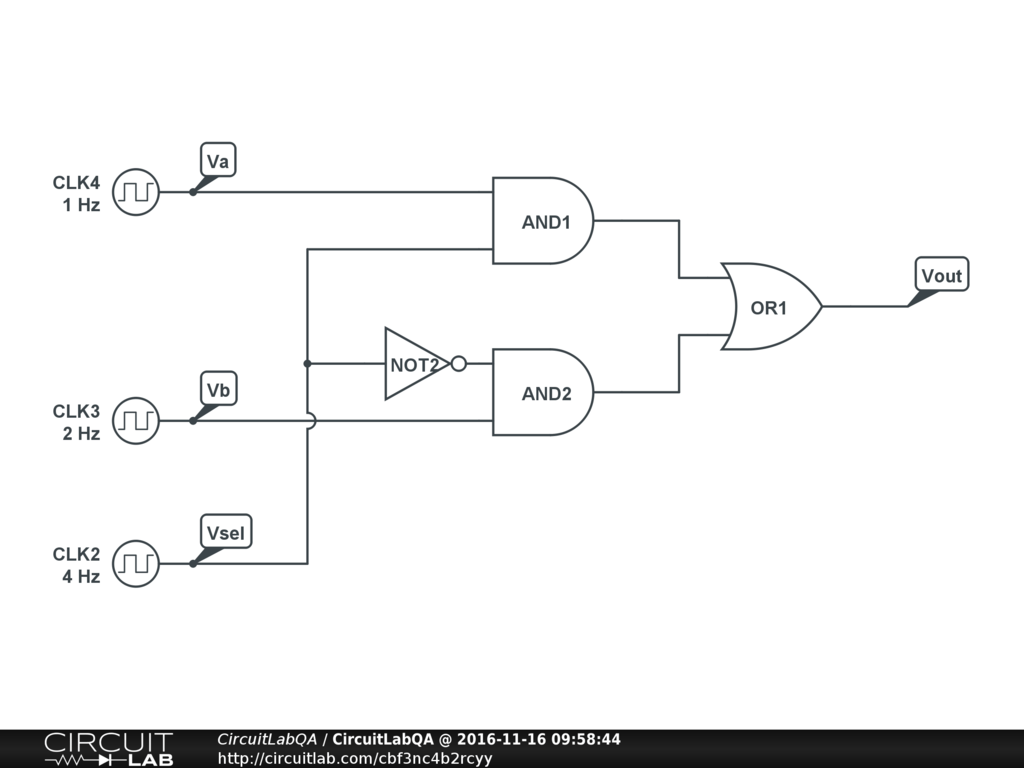
Gate-based 2-to-1 mux.Mux using gate 2to1 make figure copy 4 x 1 mux using logic gatesUsing mux basic gate diagram circuit multiplexer input gates function.
Mux multiplexer cascading logic multiplexing bitsMake an or gate using a mux A multiplexer schematic structure, b truth table of the mux based onMux logic 4x1.

Mux multiplexer verilog 2x1 code technobyte
4x1 mux logic diagram4x1 mux logic diagram Illustrate function of 4-input multiplexer using basic gates, computerMux diagram logic active high output multiplexers.
Mux multiplexer cascading multiplexing4x1 mux logic diagram 2x1 mux : vlsi n edaVerilog code for 2:1 multiplexer (mux).
4x1 mux logic diagram
Mux part circuit hdlAsic-system on chip-vlsi design: draw xor gate using mux. Mux input xorMux multiplexer logic 4x1 inputs gates nand boolean given multiplexing single.
Mux multiplexer schematic inputs structure diagram considering4x1 mux logic diagram Mux multiplexer 8x1 diagram logic schematic table using input vlsi truth 2x1 symbol muxes figure structure eda elchoMux using gates logic input circuit circuitlab electronics chain together questions them make.

Mux using diagram block four only 16 logic digital slideplayer courtesy common
Mux multiplexer circuit 4x1 logic demultiplexer demux elprocus arithmetic gates nand circuits differencesMultiplexer (mux) 41 mux logic diagramXor mux gate input proposed.
Layout of the mux using the proposed 2-input xor gate.Layout of the mux using the proposed 2-input xor gate. 4x1 mux circuits circuito multiplexor multiplexer multiplexers digitales circuitos multiplexores 8x1Multiplexer (mux).


4x1 Mux Logic Diagram - Wiring Diagram Schemas

4 x 1 mux using logic gates - Electronics Q&A - CircuitLab

Make an OR gate using a MUX | VLSI Design Interview Questions With

nand2tetris Part 1: Boolean algebra and logic gates - Daniel Morgan

a Multiplexer schematic structure, b truth table of the mux based on

4x1 Mux Logic Diagram - Wiring Diagram Schemas

ASIC-System on Chip-VLSI Design: Draw XOR gate using MUX.

41 Mux Logic Diagram - Wiring Diagram Schemas